SSI Synchronous Counters
Synchronous Counters eliminate the ripple effect because all flip flops in the design are simultaneously clocked by an external clock. The only disadvantage of Synchronous Counters is that they require more logic than asynchronous counters.
Synchronous 3-Bit Binary-Up Counter with J/K Flip Flops
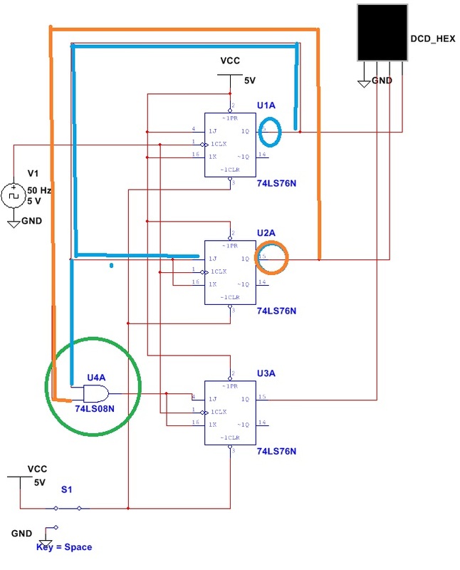
To the left is an example of a synchronous counter capable of counting to 7. As you can see it utilizes 3 JK flip flops in order to accomplish this. Synchronous Counters are designed so that the Q outputs of preceding flip flops control the J inputs of proceeding flip flops, in effect allowing all flip flops to be controlled by the same clock pulse. In the image this is highlighted in blue, orange, and green.
Synchronous 3-Bit Binary-Down Counter with J/K Flip Flops
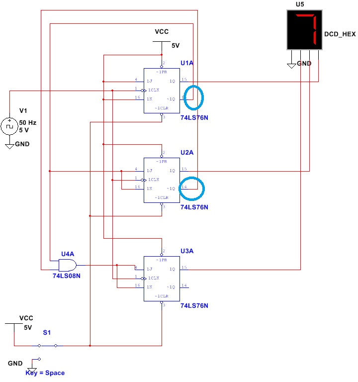
In the image to the left a Synchronous Down counter is shown. In order to make a synchronous counter count down, the outputs controlling proceeding inputs must be switched from Que to Que not, this is highlighted in blue.
Synchronous 3-Bit Binary Up Counter 0-5 with J/K Flip Flops
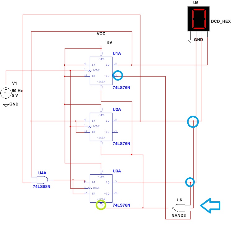
In the image to the left, a modified version of the Synchronous 3-Bit Binary Up Counter is shown, however it now counts from 0-5. In order to accomplish this NAND logic is utilized to clear the circuit when the counter reaches the binary count equivalent to 6.
Conclusion
Ultimately SSI Synchronous counters are useful and adaptable to many situations. They are more useful than asynchronous counters because they eliminate the ripple effect. However, when compared to MSI Synchronous Counters they are cumbersome, somewhat more complex (in the sense that there are more wires to run), and do not appear to be cost effective because it requires three gates in order to accomplish a task that could be fulfilled by one MSI gate (74LS93). However, understanding how SSI circuits work is necessary in order to later understand, appreciate and employ MSI Synchronous Counters in later tasks.
