Intro
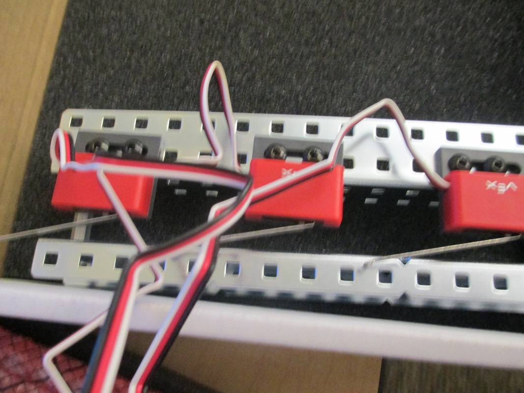
Alright, for the Paper Jam Detector Project we were asked to design a circuit that could detect a Paper Jam. Basically we have 3 switches that are spread pretty evenly throughout a printer so that only the two switches farthest away from each other can be pressed simultaneously. If a switch is pressed, indicating a paper is under it, it will output a 1, if not it will output a 0. We are supposed to design a circuit that makes a light and buzzer turn on when there is a "Jam" i.e. two switches that are adjacent to one another are pressed. The light should turn of when the Jam is removed, but the buzzer has to remain on until a button is pressed.
Brainstorming
Alright so basically I just started to design the logic I would need to make this circuit work. I created a truth table, simplified it and drew the basic circuit.
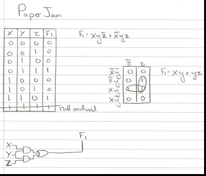
The above simple circuit provided the essential output for our circuit, (it will output a 1 when two adjacent switches are pressed). Now however, I had to figure out how to keep the buzzer going until a button is pressed.
PLD Design
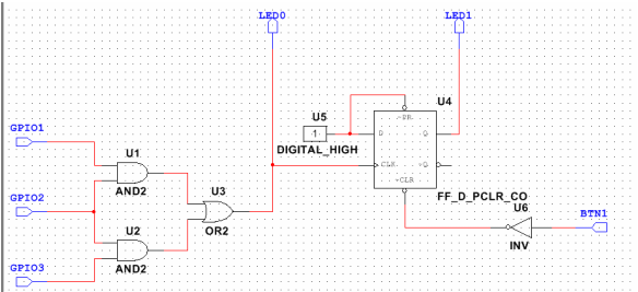
In order to keep the buzzer going I decided to use a design similar to the Event Detector in the Applications of Flip Flops Activity. As you can see, when the GPIO's (the switches) are toggled to incite the appropriate reaction (2 adjacent switches are pressed) it turns on LED0 (the light) and LED1 (the buzzer). When the GPIO's are deactivated LED0 turns off because it is linked directly to them, however LED1 continues because it is controlled by the flip flop. Because Q follows D, LED1 will continue to be activated until either D changes or PRESET and/or CLEAR turn off. So I wired an inverted button to CLEAR so that CLEAR will always receive a 1 value unless the button is pressed, thus deactivating the Buzzer.
Finished Project
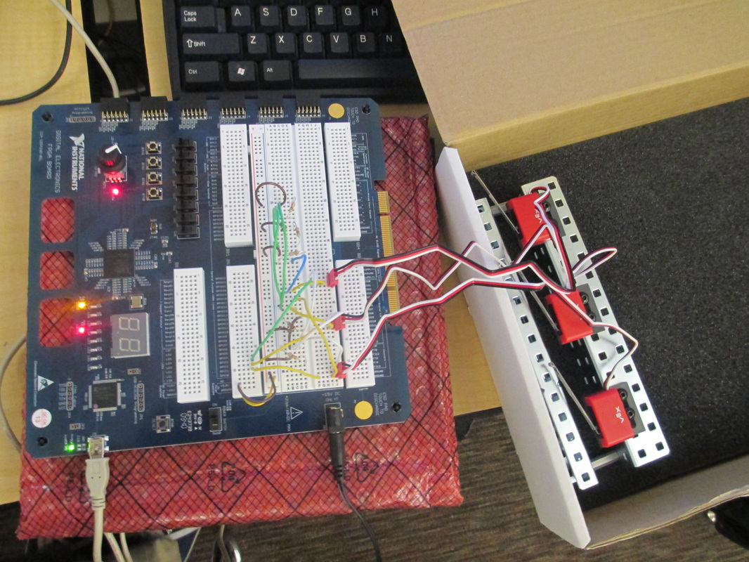
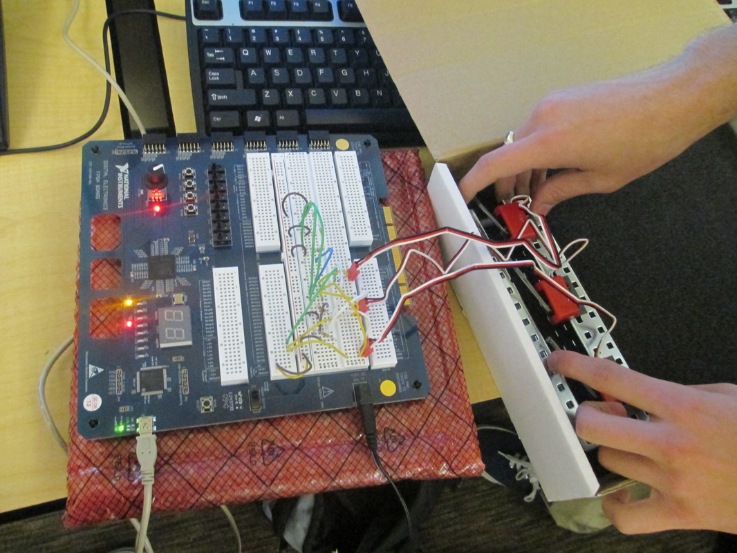
Below is a video that shows the circuit working. When two adjacent switches are pressed two LED lights switch on (one represents the buzzer, the other the light). When the switches are released one of the lights turns off while the other stays on until Button 1 is pushed. So there you go!
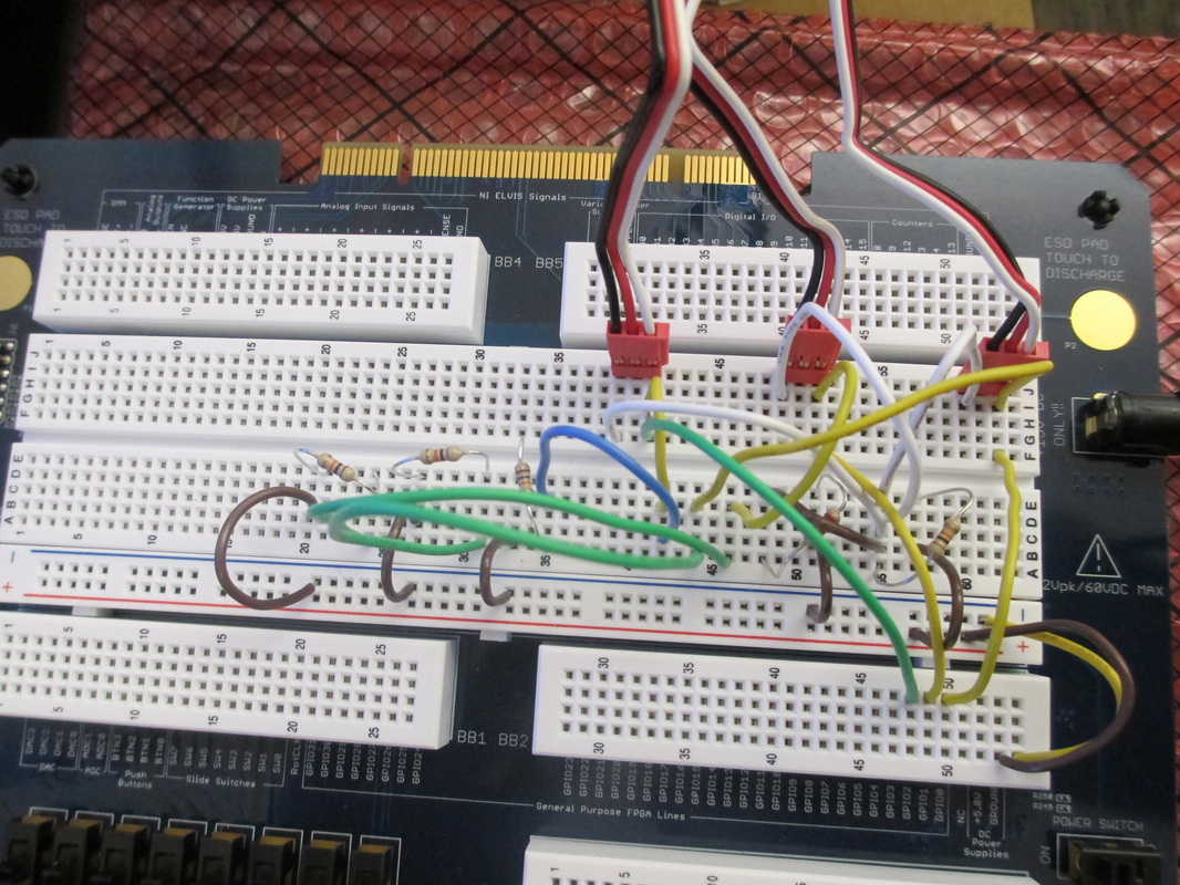
Here are some pictures of the Digital Logic Board in-case you need anymore help! Basically all of the wires are just so that appropriate GPIO's and Buttons are receiving the appropriate amount of power and resistance. A diagram of this is available to you by power-point.