Before I begin, I am going to assume you know what K-mapping, NAND, NOR, AOI, and any other Digital Electronic term I use mean because I have already explained them in previous entrees. So, if you do not know STOP and look at my other entrees like the NAND and NOR circuits, or the Voting booth. :)
Problem Statement / Constraints

Straight from the worksheet located here:
"The Acme Fireplace Company has hired you to redesign the fireplace control circuit
for their latest residential gas fireplace. The fireplace burner is equipped with four
thermal sensors that output a logic (1) whenever a flame is present. These sensors
are connected to the fireplace control circuit which outputs a (1) to the emergency
cut-off valve to keep the gas flowing (i.e., a zero will turn the gas off).
The original design of the fireplace control circuit was quite simple. For the gas valve
to remain on, all four sensors needed to output a logic (1). During field testing it was
discovered that variations in gas pressure and humidity cause the thermal sensors
to occasionally output a logic (0) even when a flame is present. This caused frequent
unnecessary shut downs and constant customer dissatisfaction.
For the redesign, is has been determined that the emergency cut-off value should
remain open as long as three of the four sensors indicate that a flame is present.
Additionally, the designers have asked you to add a second output indicator to the
control circuit. This indicator will output a logic (1) when the four sensors do not all
agree (i.e., not all on, or not all off). This indicator will be used by the service
technician to diagnose whether a faulty sensor exists."
Simply the circuit controlling Gas needs to power down when two or more sensors are off, simultaneously the fault indicator circuit needs to turn on if any of the sensors are different than the others.
Brainstorming / Calculations
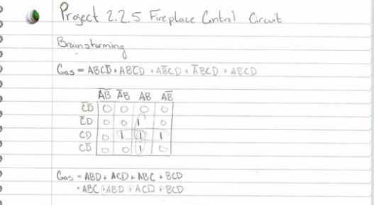
Alright so first I wrote out the unsimplified midterm equations for both the Gas and Fault Indicator circuits.
Gas = ABCD' + ABC'D + AB'CD + A'BCD + ABCD
Which was simplified using the K-map below to create the equation ...
GAS = ABC + ABD + ACD + BCD
Gas = ABCD' + ABC'D + AB'CD + A'BCD + ABCD
Which was simplified using the K-map below to create the equation ...
GAS = ABC + ABD + ACD + BCD
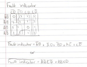
Fault Indicator = ABCD' + ABC'D + AB'CD + A'BCD + ABC'D' + AB'C'D + A'B'CD + AB'C'D' + A'B'C'D + A'B'CD' + A'BC'D'
Which was simplified using K-mapping however it produced two equations, both of which could be wired. The later was chosen as it ended up using less gates.
Fault Indicator = A'B + A'D + B'D + AC' + CD'
Fault Indicator ' = A'B'C'D' + ABCD
Which was simplified using K-mapping however it produced two equations, both of which could be wired. The later was chosen as it ended up using less gates.
Fault Indicator = A'B + A'D + B'D + AC' + CD'
Fault Indicator ' = A'B'C'D' + ABCD
Both of these circuits were then drafted, the first using NAND gates and the second using NOR.
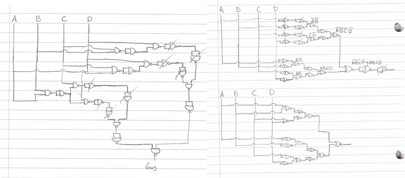
I left in my drafts in order to show how NAND and NOR gates can be canceled out. Gas circuit is on the right, Fault Indicator is on the left.
Design
To verify that my circuit worked I built it on Multisim, it did and my circuit was found to be very efficient as it used few gates.
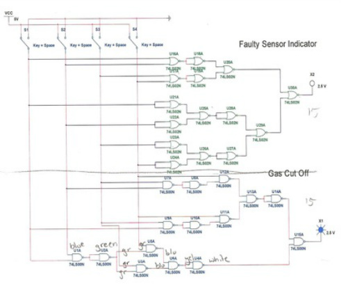
Final Design
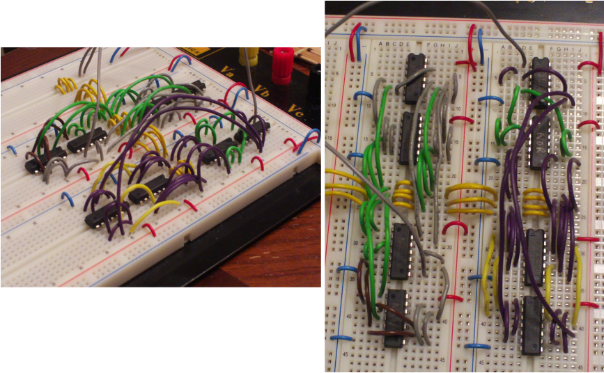
Finally I built the circuits on a breadboard, which was checked by Mr. (Unspecified Teacher).
Reflection
Alright so everything worked out once again. From this I learned how to build two circuits simultaneously (which I accidentally did already during the NAND and NOR project). However, because I already wired two circuits on the same board I new that I needed to be organized so I color coded all of my wires, and engineered a path between my gates in order to carry my inputs closer to the gates, thus allowing for a cleaner board. Many problems were encountered during this project as my bread board companion died several times and I had to re-solder it. Also my backup bread board companion died, and the entire circuit was rebuilt twice because I accidentally lost track of one of my wires and it came unplugged, causing me to take apart the whole circuit one wire at a time until I found the problem. From this I also became more confident in my abilities to write and simplify equations, design circuits, use multisim, and physically wire circuits. If I was to do this again I would have preferred to not have been stressing over this project while I was attending a funeral, missing a bunch of school, and having a bunch of make up work. But it was just a string of bad luck that I was able to work through so overall it was a successful project.
