Introduction
"In this design problem, you will have the opportunity to draw together all of the concepts and skills that you have developed pertaining to the topic of asynchronous counter design. You will design, simulate, and build a Sixty Second Timer." (3.2.4 Sixty Second Timer)
Equipment
74LS93 74LS74 74LS76 Common Cathode Seven-Segment Displays Additional logic gates as needed
|
Constraints
|
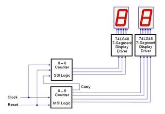
Basic design example provided by the activity sheet (3.2.4 Sixty Second Timer)
Documentation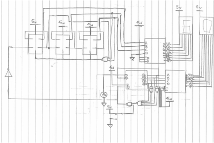
Here is a rough draft/brainstorm of the circuit drawn out on paper.
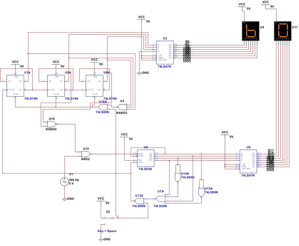
Above is the first prototype simulation circuit. It worked as expected and counted to 60.
|
Calculations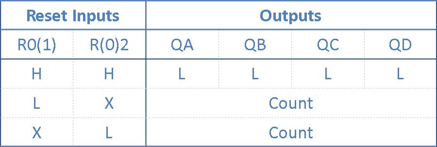
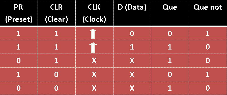
Above and below are truth tables that were used in order to understand the gates utilized in this design. MSI is on the top, while SSI is on the bottom.
|
Conclusion
Above is a video of the final circuit being used. This circuit was kind of confusing to design because it utilizes both SSI and MSI logic. In the picture of the simulation above the SSI part of the circuit is in the upper left hand corner, while the MSI part of the circuit is in the bottom left. While beginning this project my first ideas were inspired by the plan provided by the worksheet. Because SSI can only count as high as the number of flip flops (in this case D flip flops, 74ls74s) integrated in the circuit it made sense to employ SSI logic in the part of the circuit that was only required to count from 0-6. It also made sense to utilize MSI logic to count in the ones place 0-9 because it can do this with little effort and only 1 gate.
In order to accomplish the task of creating a Sixty Second Timer I began by first designing the MSI portion of the circuit. Because the MSI portion controlled the one's place, the rest of the circuit was dependent on it to carry the count. I first wired the 74LS93 (MSI Synchronous Counter) to a 74ls47 in order to convert my binary counts into the appropriate format to work on a Seven Segment display. (Between the 74ls74 I used 220 Ohm resistors in order to not blow out my display lights). I then used NAND logic in order to make the count reset after 9 rather than continue into random letters; to do this I simply wired NAND gates to function as inverters which carried the binary count of 10 (1010) to a 4 input NAND gate which then ran through another NAND gate accompanied with an SPDT switch (our reset switch) which then went to R02 (Reset #2) thus resetting the count to 0 when it reaches 9 or when the switch is engaged. *R01 is always to VCC so it doesn't really affect anything in this circuit, it does but it doesn't.
I then utilized the same output (reset output) from the last NAND gate in the MSI design in order to trigger a count in the SSI logic which was built using similar methods to the circuits on my page called SSI Synchronous Counters. The reset signal functioned as a clock in the SSI portion of the circuit which was wired (similar to the MSI logic) to a 74ls47 encoder in order to operate the Seven Segment Displays. The SPDT reset switch was then wired to the Clear inputs of all of the Flip Flops in order to make the reset switch function in the tens place as well as the ones place. The most difficult part about this part of the circuit was getting it to stop at 6 (60) rather than reset. I finally figured it out mainly through expirmentation, all you have to do is wire the Que outputs of the second and third Flip Flops into a NAND gate, then run that through an AND gate and finally run that into Input A of the MSI portion of the circuit. That ultimately halts the count. I found this project to be interesting and challenging. It was slightly annoying only in the aspect that figuring out how to make it stop took forever, however it was very cool to see both MSI and SSI logic working together in the same counter.
