Intro
Flip flops have a lot of different and useful functions and applications. Below are a few that we learned how to create and implement in class.
Event Detection Circuits
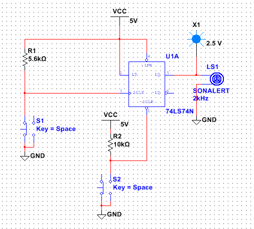
This circuit really requires a video to be at all entertaining however I do not have one. So basically what this circuit does is activate a buzzer (SONALERT). It is basically the same set up as the Paper Jam Circuit, however it only has 1 input switch to trigger the clock instead of three. Other than that if works just the same; the first switch activates the clock which allows Q to follow D (activating the buzzer). The Buzzer will continue to sound even after the first switch has been released because Q will continue to follow D. Only until Preset, Clear, or D are set to 0 will the Buzzer stop - in this circuit Clear is connected to a switch which allows it to toggle between 0 and 1 in order to stop the buzzer. Ultimately this circuit is incredibly useful although not terribly exciting.
Data Synchronizer
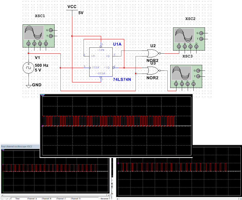
This circuit is also known as the non-overlapping signal generator. Basically it provieds two signals that are opposites of one another. It does this because the two output signals are products of nor gates activated by the clock and either Que or Que not. Below U2 is connected to clock and Que, while U3 is connected to clock and Que not, providing opposite signals.
Shift Register
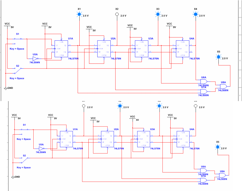
Again, another circuit that would be cooler with a video - but alas no video. The shift register circuit is pretty entertaining anyway. I used 4 JK flip-flops to create this one (actually there are two circuits below). In the first Probe 5 (X5 - the one on the far right). needed to be activated when Probes 1-4 displayed the binary count 1011. This was accomplished easily through simple AOI logic. The interesting thing about this circuit is the way that count is reached; S1 determines whether or not a 1 or a 0 will be the next output, while S2 shifts that output from X1 to X2 to X3 and to X4. This is really a form of early memory storage and can be used as such.
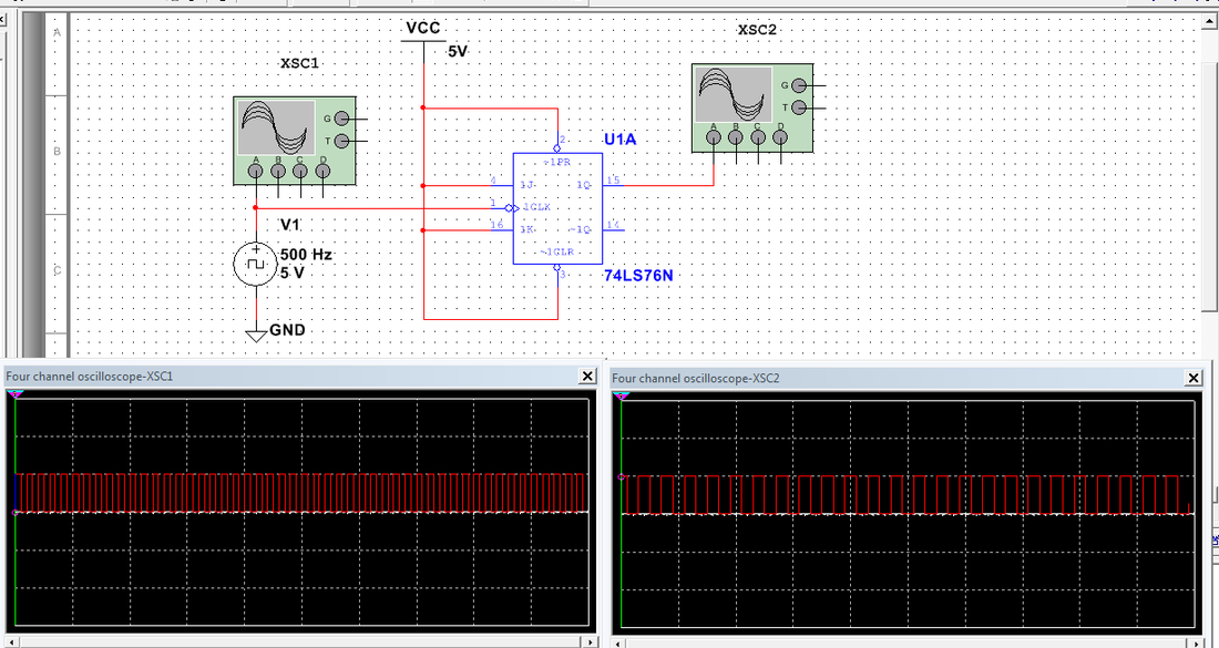
Frequency Divider
The Frequency Divider circuit is pretty straightforward. A signal traveling through a flip flop with an output following a toggling (1,1) Jay and Kay, creates an output signal that is 1 have the frequency of the original signal. While simple this circuit is very important while slowing frequencies, and can be used to cut frequencies over and over again, i.e. (1/4, 1/8, 1/16, ... etc.)