Introduction
"In this design project, you will have the opportunity to draw together all of the concepts and skills that you have developed pertaining to the topic of synchronous counter design. You will design, simulate and build a Now Serving Display. This is the type of display that you would commonly see at a deli counter." (3.3.4 Now Serving Display)
Equipment
74LS48 Common Cathode Seven-Segment Displays Additional logic gates as needed (I used Inverters, 74LS20, and 4 Input NAND,74LS20)
|
Constraints
|
Brainstorming/Designing
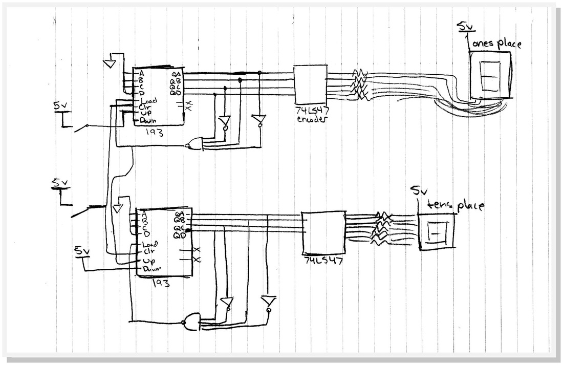
During the beginning stages of this project I referred back to previous designs that implemented the 74LS193 Integrated circuit in order to refresh my memory as well as gain new ideas. To me the problem seemed like it could be solved if I combined ideas from both 3.3.3. and the 60 Second Counter. With this idea in mind I set to drawing my first rough sketch of my design.
Prototyping/Simulating
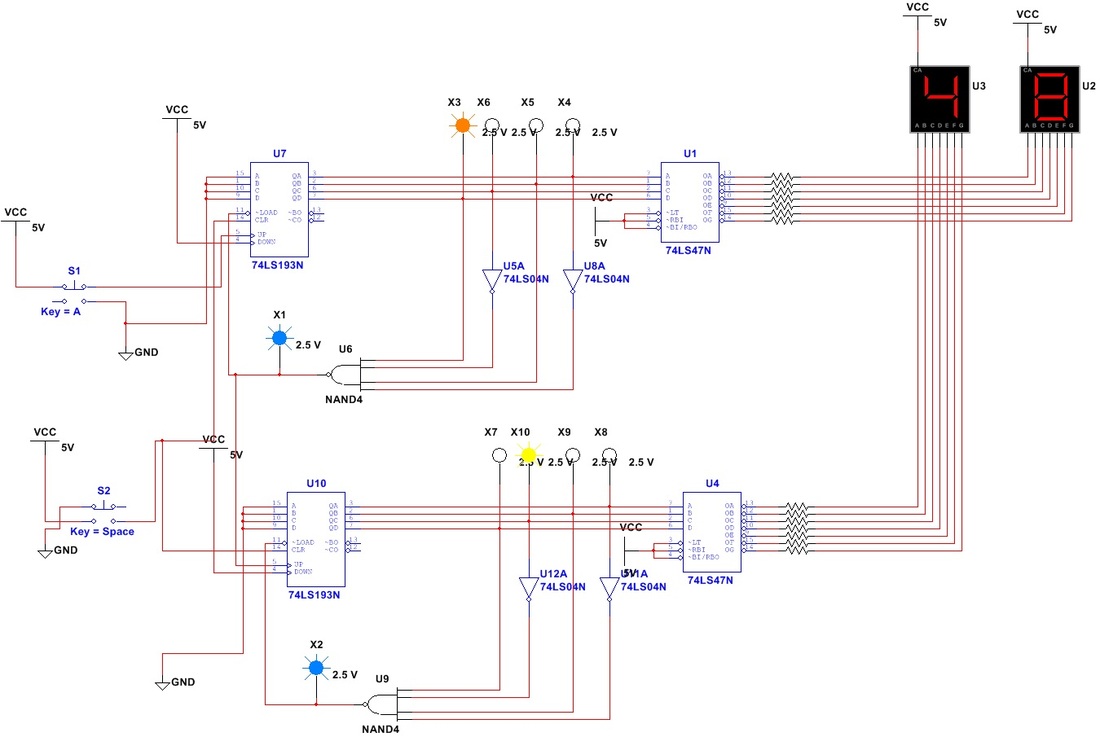
From my first sketch I created a simulation of the circuit on Multisim 2012. I had to refer to previous circuits in order to refresh my memory of switches and how they are wired to power and ground however after that there were few problems. The circuit met all criteria. Below is a video of it working. If the switch does not look like it is congruent with the numbers that is only because of the recording software I used, I clicked the switch so quickly at some points during the clip that it looks like the switch is not being clicked at all. I assure you that it is.
Physical Prototype / Final Prototype
The physical prototype of this circuit was extremely difficult to wire. To begin we were using slightly different gates than those designated in the assignment (because the school did not have those specific gates). Next we encountered something called a D Bounce, basically it just meant that our button was not going to work; it didn't interact with the rest of the circuit. To solve this Mr. Wemp read some online forums and collectively we decided to run our buttons through a D-Flip-Flop. This solution surprisingly worked. I do not understand why our simulated circuit worked while our physical prototype did not but all is well that ends well. Below are some pictures and video of the final working project.Sorry the wires are so messy! But if it is any consolation they are color coded. If you are trying to complete this project I have attached the forum note that helped us while we were wiring this. Also just a side not, you will want to turn your clock pulse up really high, for some reason the button malfunctions every once in a while if the clock pulse is to slow.
Conclusion
Honestly, this assignment made me lose faith in the 74LS193s which is very sad because they used to be my favorite. However, I think that the project would have been more successful had we had a substitute for the buttons. I don't think very many people knew how to use them and I had to experiment for a long time to get them to work, and even then they didn't always work 100%. This circuit, while it did complete its task multiple times without error, was only partially consistent. The only things that I can come up with that may cause such inaccuracy would be that there was something wrong with the buttons, a wire was short, or most likely my battery was dying. Ultimately I think with small adjustments this would be a very good circuit and I am glad that I gained experience with "realistic unforeseen delays" as it taught me how to better troubleshoot. (Sorry that the video is so spliced together, I tried to get it to run a full cycle without malfunctioning but I didn't have another battery!).
